About ECO-NIWAS 2018

1. Introduction

1.1 India’s Intended Nationally Determined Contributions (INDCs) aim to reduce the emissions intensity of its gross domestic product (GDP) by 33 to 35 percent by 2030 from 2005 level. Any effort to achieve this target is contingent upon the increase in efficiency of energy use across all sectors, especially in the building sector. The building sector in India consumes over 30% of the total electricity consumed in the country annually and is second only to the industrial sector as the largest emitter of greenhouse gases (GHGs).

1.2 Out of the total electricity consumed in the building sector, about 75% is used in residential buildings. The gross electricity consumption in residential buildings has been rising sharply over the years. For instance, the consumption figure rose to about 260 TWH in 2016-17 from about 55 TWH in 1996-97. That is an increase by more than four times in 20 years. Projections show it rising to anywhere between 630 and 940 tWh by 2032. Among various reasons, increased use of decentralized room-based air-conditioning units in homes for thermal comfort is an important reason contributing to this rapid increase in the electricity use in residential buildings. The demand for air-conditioning will continue its exponential growth with improvement in household incomes and will become the dominant contributor of GHG emissions nation-wide owing to increased electricity consumption. This situation calls for an immediate energy conservation action plan.

1.3 Energy codes for new buildings are an important regulatory measure for ushering energy efficiency in the building sector. They are particularly relevant for countries like India where the building stock is growing rapidly. The commercial sector among buildings has been addressed by the Energy Conservation Building Code (ECBC) for Commercial Buildings. Given the current and anticipated rapid growth in the resi-dential building stock across India and the consequent opportunities as well as the necessity for energy conservation in this sector, the Energy Conservation Code for residential Buildings is established by the Ministry of Power.

1.4 Building envelope consists of walls, roof, and fenestration (openings including windows, doors, vents, etc.). Design of building envelope influences heat gain/loss, natural ventilation, and daylighting, which, in turn, determines indoor tempera-tures, thermal comfort, and sensible cooling/heating demand.

1.5 Most parts of India have cooling-dominated climates. Consideration of heat gain is often not given sufficient importance during residential building design. It is seen that current practices of residential building design and construction show a large variation in heat gains and hence in the sensible cooling demand. Depending on the envelope design and construction adopted for residential buildings located in a particular climate zone, the minimum and maximum sensible cooling demand can vary by as much as 1:3.

1.6 Energy Conservation Building Code – Residential (ECBC-R) (Part I: Building Enve-lope) has been prepared to set minimum building envelope performance stan-dards to limit heat gains (for cooling dominated climates) and to limit heat loss (for heating dominated climates), as well as for ensuring adequate natural ventilation and daylighting potential. the code provides design flexibility to innovate and vary important envelope components such as wall type, window size, type of glazing, and external shading to windows to meet the compliance.

1.7 The code is applicable to all residential buildings and residential parts of ‘mixed land-use projects’, both built on a plot area of ≥500 m2. However, states and municipal bodies may reduce the plot area based on the prevalence in their area of jurisdiction. This provision is kept to take into account the prevalent plot sizes and housing types in different states, enabling the inclusion of a greater percentage of new multi-dwelling unit residential buildings within the scope of this code. (Please refer paragraph 2.4.)

1.8 Building envelope has the highest impact on thermal comfort, and consequently on the energy use in residential buildings. The envelope is also a permanent compo-nent of the building with the longest life cycle. An early introduction of this code would improve the design and construction of new residential building stock being built currently and in the near future, thus significantly curtailing the anticipated energy demand for comfort cooling in times to come. This critical investment in envelope design and construction made today will reap benefits of reduced GHG emissions for the lifetime of the buildings.

1.9 Part I – Building Envelope of ECBC-R is designed in a simple-to-apply format, requiring only simple calculations based on inputs from the architectural design drawings of buildings. This can be used by architects and engineers and will not require any simulation software. This also enables the code to be readily adopted in the building bye-laws. A compliance tool is also available on BEE website to aid in the calculations and compliance check.

1.10 Part I – Building Envelope is the first part of ECBC-R. It is envisaged that new parts will be added to address other aspects, such as energy efficiency in electro-mechanical equipment for building operation, renewable energy generation, and embodied energy of building materials and structural systems.

Scope

2.1 The code sets minimum performance standards for building envelope to limit heat gains (for cooling dominated climates) and limit heat loss (for heating dominated climates) through it. The code gives the following provisions to this effect:

  1. Building Envelope (except roof)
    1. Maximum value of residential envelope transmittance value (RETV) for building envelope (except roof) applicable for four climate zones, namely, Composite Climate, Hot-Dry Climate, Warm-Humid Climate, and Temperate Climate.
    2. Maximum value of thermal transmittance of building envelope (except roof) for Cold Climate zone (Uenvelope,cold).
  2. Roof: Maximum value of thermal transmittance of roof (Uroof) for all climate zones.

2.2 The code sets minimum building envelope performance standard for adequate natural ventilation potential by specifying minimum openable window-to-floor area ratio (WFRop)

2.3 The code sets minimum building envelope performance standard for adequate daylight potential by specifying minimum visible light transmittance (VLT) for the non-opaque building envelope components.

2.4 The code applies to (a) ‘Residential buildings’ built on a plot area ≥500 m2 and (b) Residential part of ‘Mixed land-use building projects’, built on a plot area of ≥500 m2.


‘Residential building’ includes any building in which sleeping accommodation is provided for normal residential purposes with or without cooking or dining or both facil-ities. this definition includes:

  1. One or two family private dwellings: these shall include any private dwelling, which is occupied by members of one or two families and has a total sleeping accommo-dation for not more than 20 persons.
  2. Apartment houses: these shall include any building or structure in which living quarters are provided for three or more families, living independently of each other and with independent cooking facilities. This also includes ‘Group Housing’.

The following are excluded from the definition of ‘residential building’ for the purpose of this code.

  1. Lodging and rooming houses: These shall include any building or group of buildings under the same management in which separate sleeping accommodation on transient or permanent basis, with or without dining facilities but without cooking facilities for individuals, is provided. This includes inns, clubs, motels, and guest houses.
  2. Dormitories: These shall include any building in which group sleeping accommodation is provided, with or without dining facilities for persons who are not members of the same family, in one room or a series of closely associated rooms under joint occupancy and single management. For example, school and college dormitories, students, and other hostels and military barracks.
  3. Hotels: These shall include any building or group of buildings under single management, in which sleeping accommodation is provided, with or without dining facilities.

CODE PROVISIONS

3.1 Openable Window-to-Floor Area Ratio (WFRop)

3.1.1 Openable window-to-floor area ratio (WFRop) indicates the potential of using external air for ventilation. Ensuring minimum WFRop helps in ventilation, improvement in thermal comfort, and reduction in cooling energy.

3.1.2 The openable window-to-floor area ratio (WFRop) is the ratio of openable area to the carpet area of dwelling units.

where,

WFRop: openable window-to-floor area ratio

Aopenable: openable area (m2); it includes the openable area of all windows and ventilators, opening directly to the external air, an open alcony,‘verandah’, corridor or shaft; and the openable area of the doorsopening directly into an open balcony.
Exclusions: All doors opening into corridors. External doors on ground floor, for example, ground-floor entrance doors or back-yard doors.

Acarpet: carpet area of dwelling units (m2); it is the net usable floor area of a dwelling unit, excluding the area covered by the external walls, areas under services shafts, exclusive balcony or verandah area and exclusive open terrace area, but includes the area covered by the internal partition walls of the dwelling unit.

3.1.3 The openable window-to-floor area ratio (WFRop) shall not be less than the values given in table 1.

Table 1 Minimum requirement of window-to-floor area ratio (WFRop)
Climatic zone Minimum WFRop (%)
Composite 12.50
Hot-Dry 10.00
Warm-Humid 16.66
Temperate 12.50
Cold 8.33
SOURCE Adapted from Bureau of Indian Standards (BIS). 2016. National Building Code of India 2016.New Delhi: BIS.

3.2 Visible Light Transmittance (VLT)

3.2.1 Visible light transmittance (VLT) of non-opaque building envelope components (transparent/translucent panels in windows, doors, ventilators, etc.), indicates the potential of using daylight. Ensuring minimum VLT helps in improving daylighting, thereby reducing the energy required for artificial lighting.

3.2.2 The glass used in non-opaque building envelope components (transparent/trans-lucent panels in windows, doors, etc.) shall comply with the requirements given in table 2. The VLt requirement is applicable as per the window-to-wall ratio (WWR) of the building. WWR is the ratio of the area of non-opaque building envelope compo-nents of dwelling units to the envelope area (excluding roof) of dwelling units
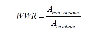
Table 2 Minimum visible light transmittance (VLT) requirement
Window-to-wall ratio (WWR) Minimum VLT
0-0.30 0.27
0.31-0.40 0.20
0.41-0.50 0.16
0.51-0.60 0.13
0.61-0.70 0.11
SOURCE Bureau of Indian Standards (BIS). 2016. National Building Code of India 2016. New Delhi: BIS.

3.3 Thermal Transmittance of roof (Uroof)

3.3.1 Thermal transmittance (Uroof) characterizes the thermal performance of the roof of a building. Limiting the Uroof helps in reducing heat gains or losses from the roof, thereby improving the thermal comfort and reducing the energy required for cooling or heating.

3.3.2 Thermal transmittance of roof shall comply with the maximum Uroof value of 1.2 W/m2.K.

3.3.3The calculation shall be carried out, using Equation 3 as shown below.

where,

Uroof: thermal transmittance of roof (W/m2.K

Aroof: total area of roof (m2)

Ui: thermal transmittance values of different roof constructions (W/m2.K)

Ai: areas of different constructions (m2)

3.4 Residential envelope transmittance value (RETV) for building envelope (except roof) for four climate zones, namely, composite climate, Hot-Dry climate, Warm-Humid climate, and Temperate climate

3.4.1 Residential envelope heat transmittance (RETV) is the net heat gain rate (over the cooling period) through the building envelope (excluding roof) of the dwelling units divided by the area of the building envelope (excluding roof) of the dwelling units. Its unit is W/m2.

RETV characterizes the thermal performance of the building envelope (except roof). Limiting the RETV value helps in reducing heat gains from the building envelope, thereby improving the thermal comfort and reducing the electricity required for cooling.

RETV formula takes into account the following:

  1. Heat conduction through opaque building envelope components (wall, opaque panels in doors, windows, ventilators, etc.),
  2. Heat conduction through non-opaque building envelope components (trans-parent/translucent panels of windows, doors, ventilators, etc.),
  3. Solar radiation through non-opaque building envelope components (transpar-ent/translucent panels of windows, doors, ventilators, etc.)

3.4.2 The RETV for the building envelope (except roof) for four climate zones, namely, Composite Climate, Hot-Dry Climate, Warm-Humid Climate, and Temperate Climate, shall comply with the maximum RETV of 15 W/m2.

3.4.3 The RETV calculation of the building envelope (except roof) shall be carried out, using Equation 4 as shown below.
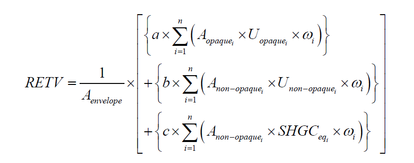
where,

Aenvelope: envelope area (excluding roof) of dwelling units (m2). It is the gross external wall area (includes the area of the walls and the openings such as windows and doors).

Aopaquei: areas of different opaque building envelope components (m2)

Uopaquei: thermal transmittance values of different opaque building envelope components (W/m2.K)

Anon-opaquei: areas of different non-opaque building envelope components (m2)

Unon-opaquei: thermal transmittance values of different non-opaque building envelope components (W/m2.K)

SHGCeqi: equivalent solar heat gain coefficient values of different non-opaque building envelope components (refer to Annexure 7)

ωi: orientation factor of respective opaque and non-opaque building envelope components; it is a measure of the amount of direct and diffused solar radiation that is received on the vertical surface in a specific orientation (values are given in Annexure 6)

The coefficients of RETV formula, for different climate zones (for classification, refer to Annexure 2), are given in Table 3.

Table 3 Coefficients (a, b, and c) for RETV formula
Climate zone a b c
Composite 6.06 1.85 68.99
Hot-Dry 6.06 1.85 68.99
Warm-Humid 5.15 1.31 65.21
Temperate 3.38 0.37 63.69
Cold Not applicable (Refer Section 3.5)

3.5 Thermal transmittance of building envelope (except roof) for cold climate (Uenvelope,cold)

3.5.1 Thermal transmittance (Uenvelope,cold) characterizes the thermal performance of the building envelope (except roof). Limiting the Uenvelope,cold helps in reducing heat losses from the building envelope, thereby improving the thermal comfort and reducing the energy required for heating.

Uenvelope,cold takes into account the following:

  1. Heat conduction through opaque building envelope components (wall, opaque panels in door, window, ventilators, etc.)
  2. Heat conduction through non-opaque building envelope components (trans-parent/translucent panels in windows, doors, ventilators, etc.).

3.5.2 The thermal transmittance of the building envelope (except roof) for cold climate shall comply with the maximum of 1.8 W/m2.K.

3.5.3 The calculation of the building envelope (except roof) shall be carried out, using Equation 5 as shown below.

where,

Uenvelope,cold: thermal transmittance of building envelope (except roof) for cold climate (W/mm2.K)

Aenvelope: envelope area (excluding roof) of dwelling units (m2). It is the gross external wall area (includes the area of the walls and the openings such as windows and doors)

Ui: thermal transmittance of different opaque and non-opaque building envelope components (W/m2.K)

Ai: area of different opaque and non-opaque opaque building envelope components (m2)

CODE COMPLAINCE

4.1 The code is designed in a simple-to-apply format, requiring only simple calculations based on inputs from the architectural design drawings of residential buildings. This can be used by architects and engineers and will not require any simulation software.

4.2 If a building project has more than one building block, each building block is required to comply with the code. However, for identical building blocks with the same orientation, the compliance has to be shown for one building block.

4.3 The steps for checking compliance for Composite Climate, Hot-Dry Climate, Warm-Humid Climate, and Temperate Climate are as follows:

Step 1: Openable window-to-floor area ratio shall comply with the minimum WFRop values as given in Table 1 of paragraph 3.1.3. For calculation of WFRop, refer Annexure 3.

Step 2: Visible light transmittance (VLT) of non-opaque building envelope components shall comply with the minimum VLT values as given in Table 2 of paragraph 3.2.2.

  1. For calculation of WWR, refer Annexure 4.
  2. Refer product specifications to know the VLT of transparent/translucent panels in windows, doors, and ventilators.

Step 3: Thermal transmittance of roof shall comply with the maximum Uroof value of 1. 2 W/m2.K (refer paragraph 3.3). to calculate the U values of roof, refer Annexure 5.

Step 4: Residential envelope transmittance value (RETV) for building envelope (except roof) shall comply with the maximum RETV of 15 W/m2 (refer paragraph 3.4)

  1. Equation 4 is to be used for the calculation of RETV, with coefficients selected from Table 3 as per the climate zone.
  2. For calculation of WWR, refer Annexure 4.
  3. For calculation of U values, refer Annexure 5
  4. For orientation factor, refer Annexure 6
  5. For calculation of Equivalent SHGC, refer Annexure 7.

An example of code compliance is given in Annexure 8 (Example 1).

4.4 The steps for checking compliance for cold climate are as follows:

Step 1: Openable window-to-floor area ratio shall comply with the minimum WFRop values as given in Table 1 of paragraph 3.1.3. For calculation of WFRop refer Annexure 3.

Step 2: Visible light transmittance (VLT) of non-opaque building envelope components shall comply with the minimum VLT values as given in Table 2 of paragraph 3.2.2.

  1. For calculation of WWR, refer Annexure 4.
  2. Refer product specifications to know the VLT of transparent/translucent panels in windows, doors, and ventilators.

Step 3: Thermal transmittance of roof shall comply with the maximum Uroof value of 1.2 W/m2.K (refer paragraph 3.3). To calculate the U values of roof, refer Annexure 5.

Step 4: Thermal transmittance of building envelope (except roof) for cold climate shall comply with the maximum value of 1.8 W/m2.K (refer paragraph 3.5).

  1. Equation 5 is to be used for the calculation of Uenvelope,cold.
  2. b) For calculation of U values, refer Annexure 5.

An example of code compliance is given in Annexure 8 (Example 2).

ANNEXURES

ANNEXURE 1 Terminology and Definitions

Building Envelope: The elements of a building that separate the habitable spaces of dwelling units from the exterior and are exposed to the ambient (i.e., exposed directly to external air and opening into balconies). It does not include walls facing open corridors and enclosed shafts, as well as walls of common services such as lifts and staircase. (See Figure 1. Dotted lines show the walls included in the definition of building envelope in this code.)
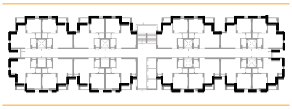
FIGURE 1 Walls included in the definition of building envelope

Carpet Area: Carpet area is the net usable floor area of a dwelling unit, excluding the area covered by the external walls, areas under services shafts, exclusive balcony or verandah area and exclusive open terrace area, but includes the area covered by the internal parti-tion walls of the dwelling unit.

Envelope Area: Envelope area (excluding roof) of dwelling units is the overall area of the building envelope (see definition ’Building Envelope’). It is the gross external wall area (includes the area of the walls and the openings such as windows and doors), with measurement taken horizontally from outside surface to outside surface and measured vertically from the top of the floor to the top of the roof.

Non-opaque Building Envelope Components: Non-opaque building envelope compo-nents include transparent/translucent panels in windows, doors, ventilators, etc.

Opaque Building Envelope Components: Opaque building envelope components include walls, opaque panels in doors, windows, ventilators, etc.

Openable Window-to-Floor Ratio (WFRop): The openable window-to-floor ratio (WFRop) is the ratio of the total openable area to the total carpet area of dwelling units. The total openable area of a dwelling unit is the addition of openable area of all windows and venti-lators, opening directly to the external air, an open balcony, ‘verandah’, corridor or shaft; and the openable area of the doors opening directly into an open balcony.

Exclusions: Doors opening into corridors and external doors on ground floor (for e.g. ground floor entrance doors or back-yard doors).

Orientation Factor (ω): It is a measure of the amount of direct and diffused solar radiation that is received on the vertical surface in a specific orientation. This factor accounts for and gives weightage to the fact that the solar radiation falling on different orientations of walls is not same.

Projection Factor, Overhang: Projection factor (overhang) is the ratio of the horizontal depth of the external shading projection to the sum of the height of a non-opaque component and the distance from the top of the same component to the bottom of the farthest point of the external shading projection, in consistent units (Figure 2).
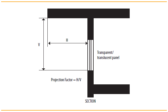
FIGURE 2 Projection factor, overhang

Projection Factor, Side Fin: Project factor (side fin) is the ratio of the horizontal depth of the external shading projection to the distance from a non-opaque component to the farthest point of the external shading projection, in consistent units (Figure 3).
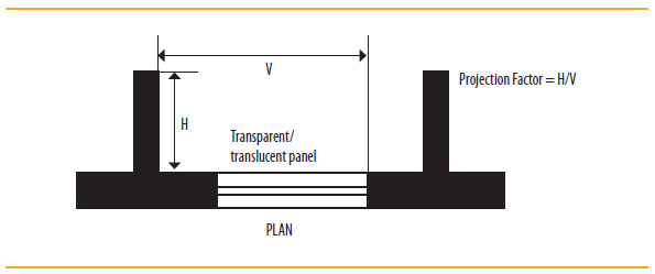
FIGURE 3 Projection factor, side fin

Residential Envelope Heat Transmittance (RETV): RETV is the net heat gain rate (over the cooling period) through the building envelope of dwelling units (excluding roof) divided by the area of the building envelope (excluding roof) of dwelling units. Its unit is W/m2.

Solar Heat Gain Coefficient (SHGC): ShGC is the fraction of incident solar radiation admitted through non-opaque components, both directly transmitted, and absorbed and subsequently released inward through conduction, convection, and radiation (Figure 4).
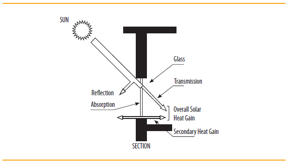
FIGURE 4 Solar heat gain through a non-opaque component

SHGC Equivalent: SHGC Equivalent is the SHGC for a non-opaque component with a permanent external shading projection. It is calculated by multiplying the External Shading Factor (ESF) with the SHGC of unshaded non-opaque component.

U Value: Thermal transmittance (U value) is the heat transmission in unit time through unit area of a material or construction and the boundary air films, induced by unit temperature difference between the environments on either side. Unit of U value is W/m2.K. The U value for a wall/roof/glazing indicates its ability to transfer heat through conduction.

Visible Light Transmittance (VLT): VLT is the ratio of the total transmitted light to the total incident light. It is a measure of the transmitted light in the visible portion of the spectrum through a material.

Window-to-Wall Ratio (WWR): WWR is the ratio of the non-opaque building envelope components area to the envelope area (excluding roof) of dwelling units.
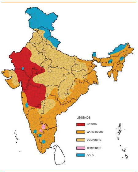

ANNEXURE 2 Climatic zone and classification of cities

FIGURE 5 Climate zone map of India
Table 4 Climate zone for major Indian cities
City Climate Type City Climate Type
Ahmedabad Hot and Dry Kurnool Warm and Humid
Allahabad Composite Leh Cold
Amritsar Composite Lucknow Composite
Aurangabad Hot and Dry Ludhiana Composite
Bengaluru Temperate Chennai Warm and Humid
Barmer Hot and Dry Manali Cold
Belgaum Warm and Humid Mangaluru Warm and Humid
Bhagalpur Warm and Humid Mumbai Warm and Humid
Bhopal Composite Nagpur Composite
Bhubaneshwar Warm and Humid Nellore Warm and Humid
Bikaner Hot and Dry New Delhi Composite
Chandigarh CompositePanjim Warm and Humid
Chitradurga Warm and Humid Patna Composite
Dehradun Composite Pune Warm and Humid
Dibrugarh Warm and Humid Raipur Composite
Guwahati Warm and Humid Rajkot Composite
Gorakhpur Composite Ramagundam Warm and Humid
Gwalior Composite Ranchi Composite
Hissar Composite Ratnagiri Warm and Humid
Hyderabad Composite Raxaul Warm and Humid
Imphal Warm and Humid Saharanpur Composite
Indore Composite Shillong Cold
Jabalpur Composite Sholapur Hot and Dry
Jagdelpur Warm and Humid Srinagar Cold
Jaipur Composite Sundernagar Cold
Jaisalmer Hot and Dry Surat Hot and Dry
Jalandhar Composite Tezpur Warm and Humid
Jamnagar Warm and Humid Tiruchirappalli Warm and Humid
Jodhpur Hot and Dry Trivandrum Warm and Humid
Jorhat Warm and Humid Tuticorin Warm and Humid
Kochi Warm and Humid Udhagamandalam Cold
Kolkata Warm and Humid Vadodara Hot and Dry
Kota Hot and Dry Veraval Warm and Humid
Kullu Cold Vishakhapatnam Warm and Humid

ANNEXURE 3 Calculation of openable window-to-floor area ratio (WFRop)

  1. Calculate the openable area of each dwelling unit (DU) by adding the openable area of all windows and ventilators, opening directly to the external air, an open balcony, ‘verandah’, corridor or shaft; and the openable area of the doors opening directly into an open balcony (doors opening into the corridors and ground-floor external doors are not included).
  2. In case exact openable area is not known, the following default values can be used:

    Table 5 Default openable area to opening area ratio
    Type of window/door/ventilator Percentage openable area
    Casement 90%
    Sliding (2 panes) 50%
    Sliding (3 panes) 67%

    Add openable areas of all dwelling units to get the total openable area.

  3. Calculate the total carpet area by adding the carpet areas of all the dwelling units (DU). It excludes the areas covered by external walls, areas under services shafts, exclusive balcony or verandah area and exclusive open terrace area, but includes the areas covered by the internal partition walls of the dwelling unit.
  4. Calculate the openable window-to-floor area ratio (WFRop) by calculating the ratio of openable area to the carpet area.

ANNEXURE 4 Calculation of window-to-wall ratio (WWR)

  1. Calculate the total non-opaque (transparent/translucent panels of windows, doors, ventilators, etc.) area of the building envelope for each dwelling unit.
  2. Add non-opaque areas of all dwelling units to get the total non-opaque area of the building block. Non-opaque components facing open corridors and enclosed shafts, as well as walls of common services such as lifts and staircase are to be excluded.

  3. Calculate the total envelope area (excluding roof) of dwelling units of the building block. For each wall of the building envelope, calculate the gross wall area (i.e., overall area of a wall including openings such as windows, ventilators, and doors, with measurement taken horizontally from outside surface to outside surface and measured vertically from the top of the floor to the top of the roof). Add the gross wall area of all walls to get the total envelope area (excluding roof) for the building. Walls facing open corridors and enclosed shafts, as well as walls of common services such as lifts and staircase are to be excluded.
  4. Calculate the window-to-wall ratio (WWR) by calculating the ratio of the total non-opaque area to the total envelope area.

ANNEXURE 5 Calculation of thermal transmittance (U value) of roof and wall

  1. Calculate the thermal resistance of each uniform material layer, which constitutes the building component, as follows:
  2. where,

    Ri is the thermal resistance of material layer i, m2.K/W

    ti is the thickness of material layer i, m

    ki is the thermal conductivity of material layer i, W/(m.K)

  3. Find the total thermal resistance, RT, as follows:
  4. where,

    RT is the total thermal resistance, m2.K/W

    Rsi is the interior surface film thermal resistance, m2.K/W

    Rse is the exterior surface film thermal resistance, m2.K/W

    R1 is the thermal resistance of material layer 1, m2.K/W

    R2 is the thermal resistance of material layer 2, m2.K/W

    R3 is the thermal resistance of material layer 3, m2.K/W

    Use these default values for calculation,

    Table 6 Values of surface film thermal resistance for U-value calculation
    Wall Roof
    All Climatic Zones Composite Climate, Hot-Dry Climate, Warm-Humid Climate, and Temperate Climate Cold Climate
    Rsi (m2.K/W) 0.13 0.17 0.10
    Rse (m2.K/W) 0.04 0.04 0.04
    SOURCE Adapted from Bureau of Energy Efficiency (BEE), 2009. Energy Conservation Building Code User Guide, New Delhi

    The thermal conductivity of commonly used building materials is given in Table 7, which can be used to calculate the thermal resistance (R value).

  5. Calculate the thermal transmittance (or the overall heat transfer coefficient or U value) of a wall or roof assembly, as follows:
  6. where,

    U is the overall heat transfer coefficient, W/m2.K

Table 7 gives typical thermal properties of commonly used building and insulating mate-rials. this is not an all-inclusive list. In case, thermal conductivity values, measured using the appropriate IS codes, are available; those can also be used for calculations.

Table 7 Thermal properties of building and insulating materials
S.No Type of material Density (kg/m3) Thermal Conductivity (W/m.K) Specific heat capacity (kJ/kg.K) Source
I Building materials
1 Solid burnt clay brick 1920 0.980 0.80 (1)
2 Solid burnt clay brick 1760 0.850 NA (1)
3 Solid burnt clay brick 1600 0.740 NA (1)
4 Solid burnt clay brick 1440 0.620 NA (1)
5 Resource efficient (hollow) brick 1520 0.631 0.65 (4)
6 Fly ash brick 1650 0.856 0.93 (2)
7 Solid concrete block 25/50 2427 1.396 0.20 (4)
8 Solid concrete block 30/60 2349 1.411 0.30 (4)
9 Aerated autoclaved concrete (AAC) block 642 0.184 1.24 (4)
10 Cement stabilized soil block (CSEB) 1700 1.026 1.03 (5)
11 Cement stabilized soil block (CSEB) 1800 1.201 1.07 (5)
12 Cement stabilized soil block (CSEB) 1900 1.303 1.07 (5)
13 Dense concrete 2410 1.740 0.88 (3)
14 Reinforced concrete cement (RCC) 2288 1.580 0.88 (3)
15 Brick tile 1892 0.798 0.88 (3)
16 Lime concrete 1646 0.730 0.88 (3)
17 Mud Phuska 1622 0.519 0.88 (3)
18 Cement mortar 1648 0.719 0.92 (3)
19 Cement plaster 1762 0.721 0.84 (3)
20 Gypsum plaster 1120 0.512 0.96 (3)
21 Cellular concrete 704 0.188 1.05 (3)
22 AC sheet 1520 0.245 0.84 (3)
23 Gl sheet 7520 61.060 0.50 (3)
24 Timber 480 0.072 1.68 (3)
25 Timber 720 0.144 1.68 (3)
26 Plywood 640 0.174 1.76 (3)
27 Glass 2350 0.814 0.88 (3)
28 Tar felt (2.3 kg/m2) 0.479 0.88 (3)
II Insulating materials
1 Expanded polystyrene 16.0 0.038 1.34 (3)
2 Expanded polystyrene 24.0 0.035 1.34 (3)
3 Expanded polystyrene 34.0 0.035 1.34 (3)
4 Foam glass 127.0 0.056 0.75 (3)
5 Foam glass 160.0 0.055 0.75 (3)
6 Foam concrete 320.0 0.070 0.92 (3)
7 Foam concrete 400 0.084 0.92 (3)
8 Foam concrete 704.0 0.149 0.92 (3)
9 Cork slab 164.0 0.043 0.96 (3)
10 Cork slab 192.0 0.044 0.96 (3)
11 Cork Slab 304.0 0.055 0.96 (3)
12 Rock wool (unbonded) 92.0 0.047 0.84 (3)
13 Rock wool (unbonded) 150.0 0.043 0.84 (3)
14 Mineral wool (unbonded) 73.5 0.030 0.92 (3)
15 Glass wool (unbonded) 69.0 0.043 0.92 (3)
16 Glass wool (unbonded) 189.0 0.040 0.92 (3)
17 Resin bonded mineral wool 48.0 0.042 1.00 (3)
18 Resin bonded mineral wool 64.0 0.038 1.00 (3)
19 Resin bonded mineral wool 99.0 0.036 1.00 (3)
20 Resin bonded mineral wool 16.0 0.040 1.00 (3)
21 Resin bonded mineral wool 24.0 0.036 1.00 (3)
22 Exfoliated vermiculite (loose) 264.0 0.069 0.88 (3)
23 Asbestos mill board 1397.0 0.249 0.84 (3)
24 Hard board 979.0 0.279 1.42 (3)
25 Straw board 310.0 0.057 1.30 (3)
26 Soft board 320.0 0.066 1.30 (3)
27 Soft board 249.0 0.047 1.30 (3)
28 Wall board 262.0 0.047 1.26 (3)
29 Chip board 432.0 0.067 1.26 (3)
30 Chip board (perforated) 352.0 0.066 1.26 (3)
31 Particle board 750.0 0.098 1.30 (3)
32 Coconut pith insulation board 520.0 0.060 1.09 (3)
33 Jute fibre 329.0 0.067 1.09 (3)
34 Wood wool board (bonded with cement) 398.0 0.081 1.13 (3)
35 Wood wool board (bonded with cement) 674.0 0.108 1.13 (3)
36 Coir board 97.0 0.038 1.00 (3)
37 Saw dust 188.0 0.051 1.00 (3)
38 Rice husk 120.0 0.051 1.00 (3)
39 Jute felt 291.0 0.042 0.88 (3)
40 Closed cell flexible elastomeric foam - NBR 40-55 0.043 1.20 (3)
NA: Not Applicable

In case, the construction has air layer, use values of thermal resistance of air layer given in Table 8 for U value calculation.

Table 8 Values of unventilated air layer thermal resistance for U-value calculation
Thickness of Air Layer (mm) Thermal resistance (m2.K/W)
Wall in All Climatic Zones Roof in composite climate, Hot and Dry climate, Warm and Humid climate, and temperate climate Roof in cold climate
5 0.12 0.10 0.10
7 0.12 0.12 0.12
10 0.14 0.14 0.14
15 0.16 0.16 0.16
25 0.18 0.18 0.17
50 0.18 0.20 0.17
100 0.18 0.20 0.17
300 0.18 0.21 0.17
SOURCE Adapted from Bureau of Energy Efficiency (BEE), 2009. Energy Conservation Building Code User Guide, New Delhi

ANNEXURE 6 Orientation Factor

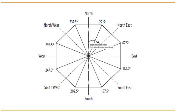
The orientation factor (ω) is a measure of the amount of direct and diffused solar radiation that is received on the vertical surface in a specific orientation. This factor accounts for and gives weightage to the fact that the solar radiation falling on different orientations of walls is not same. It has been defined for the latitudes ≥23.5 ̊N and latitudes 23.5 ̊N (Table 9). Table 9 should be read in conjunction with Figure 6.

Table 9 Orientation factor (ω) for different orientations
Orientation Orientation factor (ω)
Latitudes ≥23.5˚N Latitudes <23.5˚N
North (337.6˚–22.5˚) 0.550 0.659
North-east (22.6˚–67.5˚) 0.829 0.906
East (67.6˚–112.5˚) 1.155 1.155
South-east (112.6˚–157.5˚) 1.211 1.125
South (157.6˚–202.5˚) 1.089 0.966
South-west (202.6˚–247.5˚) 1.202 1.124
West (247.6˚–292.5˚) 1.143 1.156
North-west (292.6˚–337.5˚) 0.821 0.908
FIGURE 6 Primary orientations for determining the orientation factor ω

ANNEXURE 7 Calculation of equivalent SHGC

SHGC Equivalent is the SHGC for a non-opaque component with a permanent external shading projection (overhang and side fins). It is calculated by multiplying the External Shading Factor (ESF) with the SHGC of unshaded non-opaque component. ESF values are defined based on the projection factor (PF). The procedure for calculation is given below:

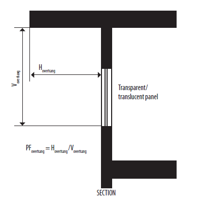
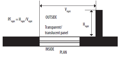
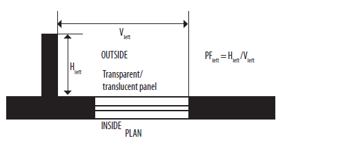
  1. Calculate the projection factor (PF) for permanent external projection, including but not limited to overhangs, side fins, box frame, verandah, balcony, and fixed cano-pies, using the formula:
    1. Projection factor, overhang: The ratio of the horizontal depth of the external shading projection (Hoverhang) to the sum of the height of a non-opaque compo-nent and the distance from the top of the same component to the bottom of the farthest point of the external shading projection (Voverhang), in consistent units.
    2. Projection factor, side/vertical fin: The ratio of the horizontal depth of the external shading projection to the distance from a non-opaque component to the farthest point of the external shading projection, in consistent units. In case of single side/vertical fin, it could be on the ‘right’ or ‘Left’ or there could be side/vertical fins on both the sides. A ‘right’ side/vertical fin would be located on the right side of the window while looking out from the building and similarly, a ‘Left’ side/vertical fin would be located on the left side of the window while looking out from the building.
  2. Select the ESF value for each shading element as:
    1. Overhang (ESFoverhang): Refer Table 10 and Table 11
    2. Side fin-right (ESFright): Refer Table 12 and Table 13
    3. Side fin-left (ESFleft): Refer Table 14 and Table 15
  3. Table 10 External Shading Factor for Overhang (ESFoverhang) for LAT ≥ 23.5˚N
    External Shading Factor for Overhang (ESFoverhang) for LAT ≥ 23.5˚N
    Orientation North North-east East South-East South South-west West North-west
    PFoverhang (337.6˚–22.5˚) (22.6˚–67.5˚) (67.6˚–112.5˚) (112.6˚–157.5˚) (157.6˚–202.5˚) (202.6˚–247.5˚) (247.6˚–292.5˚) (292.6˚–337.5˚)
    <0.10 1.000 1.000 1.000 1.000 1.000 1.000 1.000 1.000
    0.10-0.19 0.955 0.930 0.922 0.906 0.881 0.905 0.922 0.930
    0.20-0.29 0.922 0.876 0.855 0.824 0.789 0.823 0.853 0.875
    0.30-0.39 0.897 0.834 0.796 0.755 0.719 0.753 0.794 0.834
    0.40-0.490.8770.8030.7450.6970.6650.6950.7430.802
    0.50-0.590.8600.7790.7020.6520.6260.6500.7000.778
    0.60-0.690.8460.7610.6660.6170.5980.6140.6630.760
    0.70-0.790.8340.7470.6350.5900.5800.5870.6320.746
    0.80-0.890.8250.7370.6090.5690.5690.5660.6060.736
    0.90-0.990.8170.7290.5870.5540.5630.5510.5850.728
    ≥10.8100.7220.5690.5420.5590.5390.5660.721
    Table 11 External Shading Factor for Overhang (ESFoverhang) for LAT < 23.5˚N
    External Shading Factor for Overhang (ESFoverhang) for LAT < 23.5˚N
    Orientation North North-east East South-East South South-west West North-west
    PFoverhang (337.6˚–22.5˚) (22.6˚–67.5˚) (67.6˚–112.5˚) (112.6˚–157.5˚) (157.6˚–202.5˚) (202.6˚–247.5˚) (247.6˚–292.5˚) (292.6˚–337.5˚)
    <0.101.0001.0001.0001.0001.0001.0001.0001.000
    0.10-0.190.9310.9240.9220.9100.8960.9100.9220.924
    0.20-0.290.8880.8640.8550.8340.8160.8340.8540.864
    0.30-0.390.8600.8180.7970.7710.7540.7710.7960.818
    0.40-0.490.8380.7820.7470.7210.7080.7200.7460.782
    0.50-0.590.8200.7550.7050.6820.6750.6810.7050.755
    0.60-0.690.8060.7340.6700.6510.6530.6510.6700.734
    0.70-0.790.7930.7180.6410.6280.6380.6270.6400.717
    0.80-0.890.7830.7060.6160.6100.6280.6090.6150.705
    0.90-0.990.7750.6960.5960.5960.6210.5960.5950.695
    ≥10.7680.6880.5790.5850.6160.5850.5780.688
    Table 12 External Shading Factor for Side Fin-Right (ESFright) for LAT ≥ 23.5˚N
    External Shading Factor for Side Fin-Right (ESFright) for LAT ≥ 23.5˚N
    Orientation North North-east East South-East South South-west West North-west
    PFoverhang (337.6˚–22.5˚) (22.6˚–67.5˚) (67.6˚–112.5˚) (112.6˚–157.5˚) (157.6˚–202.5˚) (202.6˚–247.5˚) (247.6˚–292.5˚) (292.6˚–337.5˚)
    <0.101.0001.0001.0001.0001.0001.0001.0001.000
    0.10-0.190.9680.9420.9720.9820.9610.9650.9880.985
    0.20-0.290.9430.8940.9490.9680.9330.9340.9770.972
    0.30-0.390.9240.8550.9310.9570.9120.9070.9680.961
    0.40-0.490.9110.8240.9170.9500.8980.8840.9600.953
    0.50-0.590.8990.7980.9050.9440.8870.8650.9540.945
    0.60-0.690.8900.7770.8950.9390.8800.8490.9480.939
    0.70-0.790.8830.7620.8870.9360.8750.8370.9430.934
    0.80-0.890.8770.7500.8810.9330.8720.8270.9390.930
    0.90-0.990.8710.7390.8750.9300.8680.8190.9350.926
    ≥10.8650.7310.8700.9270.8650.8120.9320.922
    Table 13 External Shading Factor for Side Fin-Right (ESFright) for LAT<23.5˚N
    External Shading Factor for Side Fin-Right (ESFright) for LAT<23.5˚N
    Orientation North North-east East South-East South South-west West North-west
    PFoverhang (337.6˚–22.5˚) (22.6˚–67.5˚) (67.6˚–112.5˚) (112.6˚–157.5˚) (157.6˚–202.5˚) (202.6˚–247.5˚) (247.6˚–292.5˚) (292.6˚–337.5˚)
    <0.101.0001.0001.0001.0001.0001.0001.0001.000
    0.10-0.190.9620.9480.9750.9820.9620.9590.9840.984
    0.20-0.290.9340.9040.9540.9680.9320.9240.9700.970
    0.30-0.390.9130.8680.9370.9570.9110.8940.9580.959
    0.40-0.490.9000.8400.9240.9490.8960.8700.9490.950
    0.50-0.590.8880.8160.9120.9420.8850.8490.9400.942
    0.60-0.690.8790.7970.9030.9360.8770.8320.9330.936
    0.70-0.790.8720.7820.8960.9320.8720.8200.9270.931
    0.80-0.890.8660.7700.8890.9290.8670.8100.9220.927
    0.90-0.990.8600.7600.8840.9250.8630.8010.9170.923
    ≥10.8550.7520.8780.9220.8590.7940.9130.919
    Table 14 External Shading Factor for Side Fin-Left (ESFleft) for LAT ≥ 23.5˚N
    External Shading Factor for Side Fin-Left (ESFleft) for LAT ≥ 23.5˚N
    Orientation North North-east East South-East South South-west West North-west
    PFoverhang (337.6˚–22.5˚) (22.6˚–67.5˚) (67.6˚–112.5˚) (112.6˚–157.5˚) (157.6˚–202.5˚) (202.6˚–247.5˚) (247.6˚–292.5˚) (292.6˚–337.5˚)
    <0.101.0001.0001.0001.0001.0001.0001.0001.000
    0.10-0.190.9680.9850.9880.9650.9610.9820.9720.942
    0.20-0.290.9430.9720.9770.9330.9320.9670.9490.895
    0.30-0.390.9250.9610.9680.9060.9110.9570.9310.857
    0.40-0.490.9120.9530.9610.8830.8970.9490.9160.826
    0.50-0.590.9000.9460.9540.8630.8860.9430.9040.801
    0.60-0.690.8900.9390.9480.8460.8790.9380.8950.781
    0.70-0.790.8840.9350.9440.8340.8740.9350.8870.766
    0.80-0.890.8770.9310.9400.8240.8710.9320.8810.754
    0.90-0.990.8710.9270.9360.8150.8670.9290.8750.744
    ≥10.8660.9230.9320.8080.8640.9270.8700.736
    Table 15 External Shading Factor for Side Fin-Left (ESFleft) for LAT<23.5˚N
    External Shading Factor for Side Fin-Left (ESFleft) for LAT<23.5˚N
    Orientation North North-east East South-East South South-west West North-west
    PFoverhang (337.6˚–22.5˚) (22.6˚–67.5˚) (67.6˚–112.5˚) (112.6˚–157.5˚) (157.6˚–202.5˚) (202.6˚–247.5˚) (247.6˚–292.5˚) (292.6˚–337.5˚)
    <0.101.0001.0001.0001.0001.0001.0001.0001.000
    0.10-0.190.9620.9840.9840.9590.9620.9820.9750.948
    0.20-0.290.9330.9700.9700.9240.9320.9680.9540.904
    0.30-0.390.9120.9590.9580.8950.9110.9560.9370.868
    0.40-0.490.8990.9500.9490.8700.8960.9480.9240.840
    0.50-0.590.8870.9420.9410.8490.8850.9420.9130.816
    0.60-0.690.8780.9350.9330.8330.8770.9360.9030.797
    0.70-0.790.8710.9310.9280.8200.8710.9320.8960.783
    0.80-0.890.8650.9260.9230.8100.8670.9280.8900.771
    0.90-0.990.8590.9220.9180.8010.8630.9250.8840.761
    ≥10.8540.9190.9130.7940.8590.9220.8790.752
  4. Calculate the total external shading factor (ESFtotal) using the formula:
  5. where,

  6. Calculate the equivalent SHGC of the fenestration (SHGCeq) by multiplying the ShGC of the unshaded fenestration product (SHGCUnshaded) with the total external shading factor (ESFtotal), using the formula:

ANNEXURE 8 Examples of Code Compliance

Example 1: A 7-storey housing project in Rajkot is trying to comply with the residential code. there are 11 identical residential towers in this project. the carpet area of each dwelling unit (DU) is 26.6 m2.

There are three windows (W1, W2, W3) and one door (D) in each DU exposed to ambient. the windows are either fully glazed or partially glazed (glass and PVC panels) and are casement windows. the door is opaque with PVC panel. Each DU has two ventilators (V) in the bath and toilet, which face a ventilation shaft. the details of the exposed door, windows, and ventilators are given below.

FIGURE 7 Layout plan of the project (Example 1)
FIGURE 8 Plan of a typical DU (Example 1)
Table 16 Details of exposed doors, windows, and ventilators (Example 1)
Opening window/door/ventilator Opening width (m) Opening height (m) Opening area (m2) Width of glass in Opening (m) Height of glass in Opening (m) Glass area in opening (m2) Opaque area (m2)
W11.201.601.921.200.530.641.28
W20.801.301.040.800.430.350.69
W30.801.601.280.801.601.280.00
D0.752.501.870.000.000.001.87
V(2 nos)0.650.400.260.650.400.260.00

Material details are as follows:

Table 17 Details of construction material (Example 1)
Wall 200 mm AAC blocks with plaster on both sides. U-value 0.78 W/m2.K
Roof 150 mm RCC with 40 mm polyurethane foam (PUF) insulation
Glass in windows Single clear glass with SHGC 0.80, VLT 85%, and U-value 5.80 W/m2.K
PVC panel 4 mm thick PVC panel used in doors and windows. U-value 5.23 W/m2.K

Does this project comply with the code?

Compliance check:

Each of the 11 residential towers will need to comply with the code for the building project to be compliant. though the towers are identical, their orientations differ.

The longer walls of towers A-E face north-south, i.e., 0° and 180°. towers F-I face 345° and 165°. towers J and K face east-west, i.e., 90° and 270°. As per table 8 in Annexure 6, towers A-E and F-I can be considered having the same orientation. thus, for this project, compli-ance may be shown for one of towers A-I and one of towers J and K.

In this example, compliance of tower C, as marked in Figure 9, is being shown.

FIGURE 9 Building for compliance check on the layout of project (Example 1)

The longer sides of this tower face north-south. It has 112 dwelling units (DUs), 16 DUs on each floor. Half of the DUs face north and the rest face south.

Table 18 Envelope areas of the building (Example 1)
Orientation Total wall length (m), exposed to ambient Total wall height (m), exposed to ambient Envelope area (m2)
North51.5821.061086.27
South51.5821.061086.27
East31.0021.06652.86
West31.0021.06652.86
Envelope area (m2) excluding roof3478.26

Step 1: Openable window-to-floor area ratio (WFRop)

1.1: Calculation of total openable area (Aopenable)

Each flat consists of three windows, one door opening to the balcony, and two ventilators. As all of them are casement openings, 90% of the opening area is considered openable.

Table 19 Openable area calculation (Example 1)
Opening name Opening area (m2) Openable area (m2) Remarks
W1 1.92 1.73 90% openable (Table 5)
W2 1.04 0.94
W3 1.28 1.15
D (opening into balcony) 1.87 1.69
V (2 nos) 0.52 0.47
Openable area for each flat 5.97
Openable area for 112 flats (Aopenable) 668.81
1.2: Calculation of total carpet area (Acarpet)
1.3: Calculate the openable window-to-floor area ratio (WFRop)

Rajkot is in the composite climate. As per table 1, the minimum WFRop for this climate is 12.5%. thus, this project complies with this requirement.

Step 2: Visible Light Transmittance (VLT)

2.1: Calculation of window-to-wall ratio (WWR)

There are three windows and one door in each DU exposed to ambient. The windows are either fully glazed or partially glazed (glass and PVC panels). The door is opaque with PVC panel.

Table 20 Calculation of window-to-wall ratio (Example 1)
Orientation Opening name Opening area (m2) Non-opaque (glass) area in opening (m2) No. of openings Total opening area (m2) Total opening area (m2) Total non-opaque (glass) area (m2)
NorthW11.920.6456107.5235.62
NorthW21.040.355658.2419.26
NorthW31.281.285671.6871.68
NorthD1.880.0056105.000.00
SouthW11.920.6456107.5235.62
SouthW21.040.355658.2419.26
SouthW31.281.285671.6871.68
SouthD1.880.0056105.000.00
Total684.88253.16

As per Table 2, for WWR of 0.073 (range 0–0.30), the minimum required VLT is 27%. the glass used in this project has a VLT of 85% (as per certified specification for the product). Thus, this project complies with this requirement. Also, it complies with the recommended value.

Step 3: Thermal transmittance of roof (Uroof)

3.1: Calculation of thermal transmittance of roof (Uroof)

The roof of this building comprises the following material layers.

Table 21 Roof construction details (Example 1)
Material layer Thickness, t (m) Thermal conductivity, k (W/m.K) Thermal resistance of material, R= t/k (m2.K/W)
China mosaic tile 0.007 1.500 0.005
Concrete (laid to slope) 0.050 1.740 0.029
Polyurethane foam (PUF) 0.040 0.023 1.739
Cement screed 0.020 0.720 0.028
RCC slab 0.150 1.580 0.095
Internal plaster 0.015 0.720 0.021
Sum of all material thermal resistance 1.917

Total thermal resistance

Thermal transmittance of roof,

This is less than the maximum Uroof value of 1.2 W/m2.K. Hence it complies with this requirement.

Step 4: RETV of the building envelope (except roof)

4.1: Calculation of envelope area, in every orientation
Table 22 Calculation of envelope area for each orientation (Example 1)
Orientation Area (m2) U value (W/m2.K)
North Non-opaque (glass) area 126.56 5.80
Opaque area 1 (AAC wall) 743.83 0.78
Opaque area 2 (PVC panel in doors and windows) 215.88 5.23
South Non-opaque (glass) area 126.56 5.80
Opaque area 1 (AAC wall) 743.83 0.78
Opaque area 2 (PVC panel in doors and windows) 215.88 5.23
East Non-opaque (glass) area 0.00
Opaque area 1 (AAC wall) 652.86 0.78
Opaque area 2 (PVC panel in doors and windows) 0.00
West Non-opaque (glass) area 0.00
Opaque area 1 (AAC wall) 652.86 0.78
Opaque area 2 (PVC panel in doors and windows) 0.00
Total Envelope Area, Aenvelepe 3478.26

(The U values of AAC block and PVC sheet are calculated the same way as that shown for the roof. The thermal conductivity of AAC block is 0.184 W/m.K and that of PVC is 0.19 W/m.K.)

4.2: Calculation of equivalent SHGC of non-opaque openings, for each orientation
Table 23 Calculation of equivalent SHGC of non-opaque openings for each orientation (Example 1)
Orientation Name Width of Glass (m) Height of Glass (m) No.of Windows Glass Area (m2) Hoverhang (m) Voverhang (m) PFoverhang Hright (m) Vright (m) PFright Hleft (m) Vleft(m) PFleft ESFoverhang ESFright ESFleft ESFtotal SHGCeq
NorthW11.200.535635.620.400.530.750.401.200.330.401.200.330.7930.9130.9120.6540.523
NorthW2-10.800.43289.631.100.432.561.101.750.631.100.801.380.7680.8790.8540.5630.450
NorthW2-20.800.43289.631.100.432.561.100.801.381.101.750.630.7680.8550.8780.5630.450
NorthW3-10.801.602835.840.471.600.293.100.803.880.470.800.590.8880.8550.8870.6590.527
NorthW3-20.801.602835.840.471.600.290.470.800.593.100.803.880.8880.8880.8540.6590.527
SouthW11.200.535635.620.400.530.750.401.200.330.401.200.330.6380.9110.9110.5240.420
SouthW2-10.800.43289.631.100.432.561.101.750.631.100.801.380.6160.8770.8590.4530.363
SouthW2-20.800.43289.631.100.432.561.100.801.381.101.750.630.6160.8590.8770.4530.363
SouthW3-20.801.602835.840.471.600.293.100.803.880.470.800.590.8160.8590.8850.6070.486
SouthW30.801.602835.840.471.600.290.470.800.593.100.803.880.8160.8850.8590.6070.486
4.3: Calculation of RETV

Rajkot is in the composite climate zone. thus, the RETV equation, with applicable coefficients, is:

Calculation for the 3 terms are shown in table below:

Table 24 Calculation of 3 terms of RETV formula
Calculation for Term-I
Orientation Component (a) Area (m2) (b) U value (W/m2.K) (c) Orientation factor*, ω (a) x (b) x (c)
North Opaque area 1 (AAC wall) 743.83 0.78 0.659 382.34
North Opaque area 2 (PVC panel in doors and windows) 215.88 5.23 0.659 744.05
South Opaque area 1 (AAC wall) 743.83 0.78 0.966 560.46
South Opaque area 2 (PVC panel in doors and windows) 215.88 5.23 0.966 1090.66
East Opaque area 1 (AAC wall) 652.86 0.78 1.155 588.16
West Opaque area 1 (AAC wall) 652.86 0.78 1.156 588.67
Term-I Total 3954.35
Calculation for Term-II
Orientation Component (a) Area (m2) (b) U value (W/m2.K) (c) Orientation factor*, ω (a) x (b) x (c)
North Non-opaque (glass) area 126.56 5.80 0.659 483.74
South Non-opaque (glass) area 126.56 5.80 0.966 709.09
Term-II Total 1192.83
Calculation for Term-III
Orientation Component (a) Area (m2) (b) Equivalent SHGC# (c) Orientation factor*, ω (a) x (b) x (c)
North W1 35.62 0.523 0.659 12.28
NorthW2-19.630.4500.6592.86
NorthW2-29.630.4500.6592.86
NorthW3-135.840.5270.65912.45
NorthW3-235.840.5270.65912.45
SouthW135.620.4200.96614.45
SouthW2-19.630.3630.9663.38
SouthW2-29.630.3630.9663.38
SouthW3-135.840.4860.96616.83
SouthW3-235.840.4860.96616.83
Term-III Total 97.74

Substitute the values of 3 terms and envelope area in the RETV formula:

This is less than the maximum RETV of 15 W/m2. hence it complies with this requirement.

The building complies with all four requirements and hence complies with the code.

Example 2: The same project given in Example 1 is built in Shimla. All specifications of the project remain the same except that all windows (W1, W2, W3) are fully glazed and sliding. the details of the exposed door, windows, and ventilators for this project are given below.

Table 25 Details of exposed door, windows, and ventilators (Example 2)
Opening window/door/ventilator Opening width (m) Opening height (m) Opening area (m2) Width of glass in opening (m) Height of glass in opening (m) Glass area in opening(m2) Opaque area (m2)
W11.201.601.921.201.601.920.00
W20.801.301.040.801.301.040.00
W30.801.601.280.801.601.280.00
D0.752.501.870.000.000.001.87
V (2 nos)0.650.400.260.650.400.260.00

Material details are as follows:

Table 26 Details of construction material (Example 2)
Wall 200 mm AAC blocks with plaster on both sides. U-value 0.78 W/m2.K
Roof 150 mm RCC with 40 mm polyurethane foam (PUF) insulation. U-value 0.47 W/m2.K
Glass in windows Single clear glass with SHGC 0.80, VLT 85%, and U-value 5.80 W/m2.K
PVC panel 4 mm thick PVC panel used in doors. U-value 5.23 W/m2.K

Does this project comply with the code?

Compliance check:

Each of the 11 residential towers will need to comply with the code for the building project to be compliant. The compliance of one of the towers is being shown.

The longer sides of this tower face north-south. It has 112 dwelling units (DUs), 16 DUs on each floor. Half of the DUs face north and the rest face south.

Table 27 Envelope areas of the building (Example 2)
Orientation Total wall length (m), exposed to ambient Total wall height (m), exposed to ambient Gross wall area (m2)
North51.5821.061086.27
South51.5821.061086.27
East31.0021.06652.86
West31.0021.06652.86
Envelope area (m2), excluding roof 3478.26

Step 1: Openable window-to-floor area ratio (WFRop)

1.1: Calculation of total openable area (Aopenable)

Each flat consists of three windows, one door opening to the balcony, and two ventilators. As all the windows are sliding windows, 50% of the window opening area is considered openable. The door and ventilators are 90% openable.

Table 28 Calculation of openable areas (Example 2)
Opening name Opening area (m2) Openable area (m2) Remarks
W1 1.92 0.96 50% openable (Table 5)
W2 1.04 0.52
W3 1.28 0.64
D 1.87 1.69 90% openable (Table 5)
V (2 nos) 0.52 0.47
Openable area for each flat 4.28
Openable area for 112 flats (Aopenable) 478.86
1.2: Calculation of total carpet area (Acarpet)
1.3: Calculate the openable window to floor area ratio (WFRop)

Shimla is in the cold climate zone. As per Table 1, the minimum WFRop for this climate is 8.33%. thus, this project complies with this requirement.

Step 2: Visible Light Transmittance (VLT)

2.1: Calculation of window-to-wall ratio (WWR)

There are three windows and one door in each DU exposed to ambient. the windows are fully glazed. The door is opaque with PVC panel.

Table 29 Calculation of window-to-wall ratio (Example 2)
Orientation Opening name Opening area (m2) Non-opaque area in opening (m2) No. of openings Total opening area (m2) Total non-opaque area (m2)
NorthW11.921.9256107.52107.52
NorthW21.041.045658.2458.24
NorthW31.281.285671.6871.68
NorthD1.880.0056105.000.00
SouthW11.921.9256107.52107.52
SouthW21.041.045658.2458.24
SouthW31.281.285671.6871.68
SouthD1.880.0056105.000.00
Total684.88474.88

As per table 2, for WWR of 0.136 (range 0–0.30), the minimum required VLT is 27%. The glass used in this project has a VLT of 85% (as per certified specification for the product). Thus, this project complies with this requirement. Also, it complies with the recom-mended value.

Step 3: Thermal transmittance of roof (Uroof)

3.1: Calculation of thermal transmittance of roof (Uroof)

The roof of this building is the same as that of Example 1, i.e., Uroof is 0.47 W/m2.K. This is less than the maximum Uroof value of 1.2 W/m2.K. Hence it complies with this requirement

Step 4: Thermal transmittance of building envelope (except roof) for cold climatic zone (Uenvelope,cold)

Shimla is in the cold climate zone. hence, the thermal transmittance of the building enve-lope (except roof) will be calculated.

4.1: Calculation of thermal transmittance of building envelope (Uenvelope,cold)

In this case, the U values of the wall (i.e., AAC block with 15 mm plaster on both sides), the opaque door component (i.e., PVC sheet), and the non-opaque components (glass used in windows) need to be combined as per the relative areas of each.

Note:

  1. Net AAC block area = Envelope area – total opening area
  2. Opaque door area= total opening area – total non-opaque area
  3. U values of the AAC block and the PVC sheet are calculated the same way as that shown for the roof. the thermal conductivity of AAC block is 0.184 W/m.K and that of PVC is 0.19 W/m.K
  4. U value of the glass used is given as 5.80 W/m2.K (as per certified specification for the product)

This is less than the maximum Uenvelope,cold value of 1.8 W/m2.K. Hence it complies with this requirement.

The building complies with all four requirements and hence complies with the code.

ANNEXURE 9 Guidelines for Design for natural Ventilation

This annexure provides a simple and illustrative interpretation of provisions for the location of windows in a room and its impact on natural ventilation. A detailed design guideline for natural ventilation is available in the NBC 2016 (Volume II, Part 8 Building Services, Section 1 Lighting and Natural Ventilation).

The code gives the following provision for minimum WFRop values for natural ventilation (Table 1, Section 3.1):

Table 30 Minimum requirement of window-to-floor area ratio, WFRop
Climatic Zone Minimum WFRop (%)
Composite 12.50
Hot-Dry 10.00
Warm-Humid 16.66
Temperate 12.50
Cold 8.33
SOURCE Bureau of Indian Standards (BIS). 2016. National Building Code of India 2016. New Delhi: BIS.

Openable window-to-floor area ratio (WFRop) indicates the potential of using external air for ventilation. The openable area allows external air, when the ambient temperature is cooler than the inside air, into the internal spaces, which helps in ventilation, improvement in thermal comfort, and consequent reduction in cooling energy.

This openable area can be distributed on the external wall in a number of ways. rooms may have openings on only one external wall or multiple external walls (usually two external walls). Some guidelines for design of these openings are given below. It is to be noted that internal doors cannot be relied for enhancing ventilation and are assumed to be closed.

  1. Distribution of the openable area on the external walls of a dwelling unit must be done to maximize cross-ventilation, i.e., the air inlet and outlet openings should be separate and positioned on different walls in a way that optimizes the air flow path through the space. This can be done by placing openings on adjacent walls or on opposite walls, where possible (Figure 10).
  2. FIGURE 10 Openings on adjacent or opposite external walls for cross ventilation (Guideline)
  3. In rooms that have openable area on only one external wall, cross ventilation can be achieved by having an opening at a higher level on one of the internal walls (Figure 11). This will enhance cross ventilation through the habitable space. This principle can be extended from room to room, for instance, from a bedroom into a living room which is cross-ventilated, thus enhancing cross ventilation through the entire dwelling unit.
  4. FIGURE 11 Openings on external wall and internal wall for cross ventilation (Guideline)
  5. In rooms with only one external wall, and where cross ventilation is not possible (see point 2, above), provision of multiple windows on the external wall is preferred to that of a single window (Figure 12). The farther apart these windows are placed on the wall, the better is the effect of air movement across the room.
  6. FIGURE 12 Two windows on single external wall (Guideline)
  7. Adding a ventilator above the windows on the external wall helps increase the rate of convective heat exchange (Figure 13). This is especially helpful in cases where windows are available on only one external wall and there is no means of cross ventilation.
  8. FIGURE 13 Adding ventilators above windows improves ventilation especially when only single external wall is available for openings (Guideline)

The following illustrative diagrams recommend good design strategies to help achieve better air exchange and increase the rate of heat loss through the buildings.

Single-sided ventilation

Case 1: Room with only one opening on the external wall

Addition of ventilator at an upper level increases the rate of convective heat exchange with the outside air.

Case 2: Room with multiple openings on the external wall

Cross ventilation

Case 1: Room with openings on both the external wall and another internal or external wall.

Comparison

For the same ratio of area of openings to floor area of a room, the thermal heat exchange increases as the number of openings increases on the wall. It is thus recommended to have openable ventilators to aid better ventilation.

ANNEXURE 10 Cool Roof and Roof Gardens

A cool roof is one that reflects most of the incident solar radiation and efficiently emits some of the absorbed radiation back into the atmosphere, instead of conducting it to the building below. The term specifically refers to the outer layer or exterior surface of the roof, which acts as the key reflective surface. A cool roof minimizes the solar heat gain of a building by first reflecting a considerable amount of incoming radiation and then by quickly re-emitting the absorbed portion. Cool roof encompasses an extensive array of applications including roof coatings, colours, textures, finishes such as broken china mosaic, tiles, and even metals.

However, cool roofs are not to be seen as an alternative to the thermal transmittance requirement of the roof (Uroof) as given in this code. It is encouraged to have any cool roof application over a roof assembly complying with the maximum thermal transmittance value given in the code.

Defining a cool roof

The ‘coolness’ of a roof is influenced by its solar reflectance and thermal emittance.

  1. Solar reflectance: Solar reflectance is the ratio of solar radiation reflected by a surface to the solar radiation incident upon it. Solar reflectance is measured on a scale of 0 to 1. A reflectance value of 0 indicates that the surface absorbs all incident solar radiation, and a value of 1 denotes a surface that reflects all incident solar radiation. The term ‘albedo’ is often used inter-changeably with solar reflectance.
  2. Thermal emittance: Thermal emittance is the relative ability of a material to reradiate absorbed heat as invisible infrared radiation. Emittance, measured from 0 to 1, is defined as the ratio of the radiant flux emitted by a body to that emitted by a black body at the same temperature and under the same conditions.

According to ECBC 2017 cool roof requirement, roofs with slopes less than 20 degrees shall have an initial solar reflectance of at least 0.6 and an initial emittance of 0.9.

The Solar Reflectance Index (SRI) is a term that incorporates both solar reflectance and emittance in a single value and quantifies how hot a surface would get relative to stan-dard black and standard white surfaces. It is the ability of a material to reject solar radia-tion, as shown by a small temperature rise.The SRIs of a standard black surface (having reflectance of 0.05 and emittance of 0.9) and a standard white surface (of reflectance 0.8 and emittance 0.9) are taken as 0 and 100, respectively.

IGBC Green homes requires a minimum SRI value of 78 for roof slopes with gradient ≤1:6 and 29 for steeper roof.

For more detailed information on cool roof, please refer Cool roofs for Cool Delhi: Design Manual.

Roof gardens

In the case of roofs with roof gardens on earth fill for plantation or lawn, the thermal resistance of the earth fill can be taken into the calculation of the thermal transmittance (U value) of the roof. Some of the heat absorbed by the earth fill is also released into the atmosphere due to evapotranspiration of irrigation water from the roof garden, thus giving additional benefit.